
Thermoelectric generators
1. General information
Typically, thermoelectric generators (TEG) find their applying in applications where it is necessary to obtain a maintenance-free power supply of low-power electronic equipment where there is a permanent temperature difference.
Thermoelectric generators find more and more applications in various fields of human activity, such as:
- feeding of autonomous equipment;
- Automotive industry;
- medicine;
- space industry;
- devices for household use.
Thermoelectric generator module (TGM) is a solid-state semiconductor device that converts thermal energy into electrical energy. It composed of two ceramic plates with semiconductor crystalline pellets connected electrically in series between them.
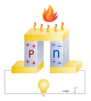
The operating principle of the thermoelectric generator is based on the Seebeck effect, the essence of which is the occurrence of EMF that is solely a consequence of the temperature difference at the junctions of the thermoelectric couple (Figure 1). Therefore, if we have a reliable heat source we can obtain reliable electric power source as well.
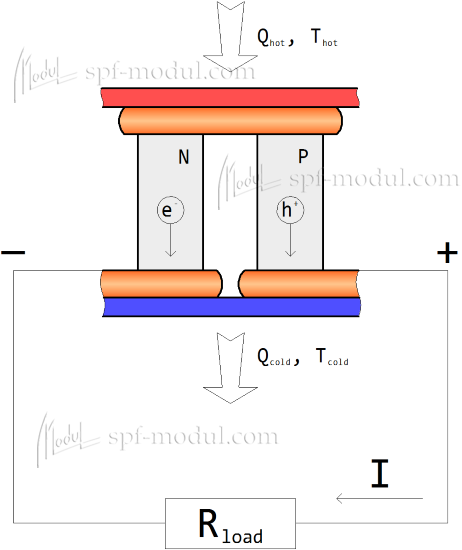
Figure 1 - The principle of the thermoelectric generation.
In the standard version, the thermoelectric generator is a heat receiver (metal plate, air or liquid heat exchanger), a thermoelectric generator module and a heat dissipation system (air or liquid).
The advantage of such sources of electrical energy over the classical ones is a long service life without the need for additional maintenance, a simple system for converting the received electric power, the possibility of waste heat usage, the ability to use for any spatial orientation, small overall dimensions.
When choosing a thermoelectric generator module, in order to obtain the required parameters under certain conditions, it is necessary to adhere the following provisions.
2. Background of TGM choice
If temperature difference on the faces of the thermoelectric generator modules (TGM) is applied, electric potential difference Uoc will appear.
Once a load is connected to the terminals of the TGM, a current start to flow through the circuit, value of which could be calculated by the formula:

where:
Uoc – open-circuit current;
Rin – internal TGM resistance;
Rload – load resistance.
Power on load could be calculated by formula:

To obtain maximum power, the resistance of the optimum load must be equal to the TGM internal resistance (Ropt=Rin).
In this case, the current and voltage at the optimum load is calculated as:
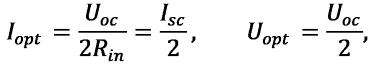
where Isc – short circuit current.
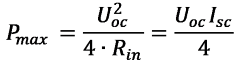
The power on the optimum load could be calculated by the following formula:
Depending on the task, the generator module can be used in two modes:
1. Maximum power mode is a mode that is usually used when converting waste heat into electrical energy.
2. The maximum efficiency mode is the mode at which the heat passing through the module is maximally used when converting it into electric energy.
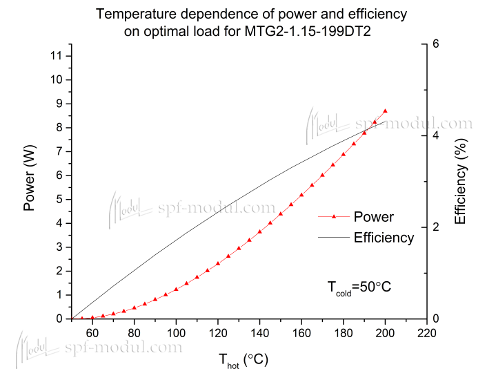
Figure 2 - Dependence of power and efficiency on temperature difference
Maximum efficiency of energy conversion by TGM could be obtained with a load resistance of Rη max, rather than Ropt (Rmaxη≠Ropt, Figure 2).
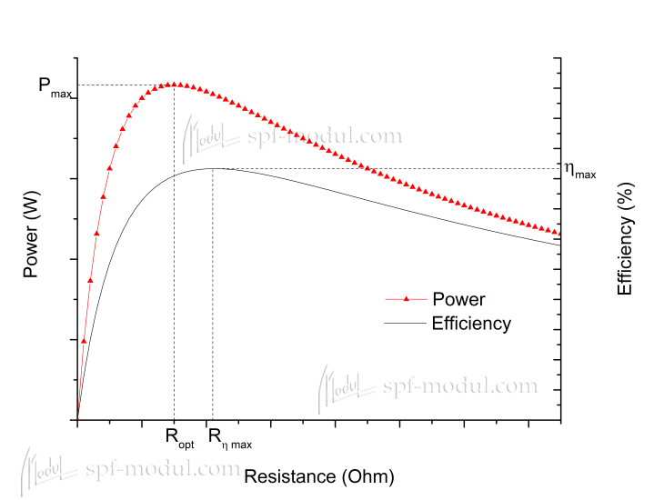
Figure 3 - Power and TGM efficiency vs. load resistance
The open circuit voltage, TGM resistance and power output will depend on the temperature at the hot and cold faces of the TGM (Figure 4-6).
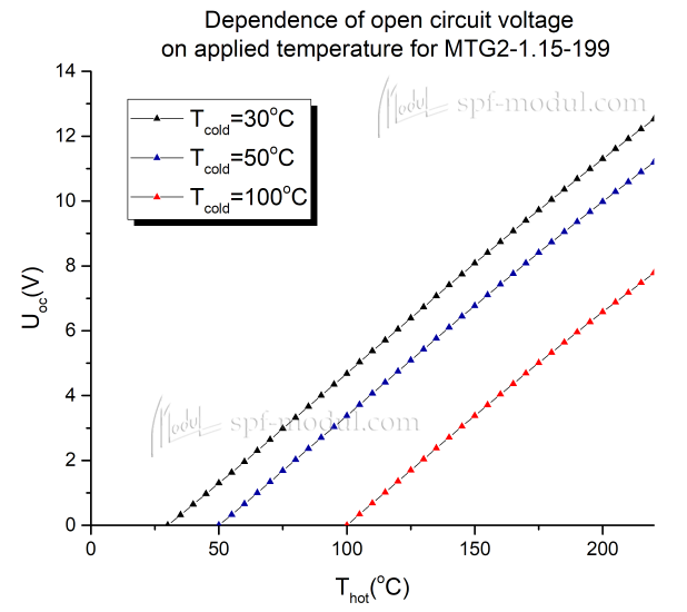
Figure 4 - Dependence of the open-circuit voltage on the temperature on the faces of the module
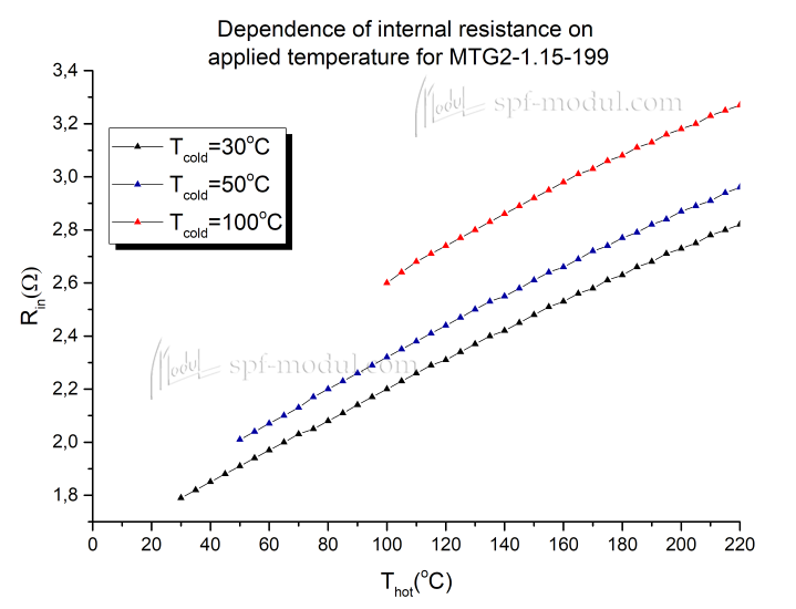
Figure 5 - Dependence of internal resistance on temperatures on the faces of TGM
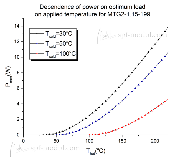
Figure 6 - Dependence of power on the optimal load on the temperature on the faces of the module
When the modules are connected in series-parallel battery of n parallel circuits with m modules in series (Figure 6), the thermo-EMF and internal battery resistance could be calculated by the following formulas:

where:
Uoc – open-circuit current of individual TGM;
Rin – internal resistance of individual TGM;
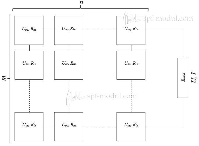
Figure 7 – Series-parallel connection of TGM
In this case, the current, voltage and power on optimum load, could be calculated as:


where:
Uoc, Isc, Pmax are the open circuit voltage, short circuit current and power on the optimum load of each TGM respectively.